
Learning Objectives
By the end of this section, you will be able to:
- Describe the arrangement of atoms and ions in crystalline structures
- Compute ionic radii using unit cell dimensions
- Explain the use of X-ray diffraction measurements in determining crystalline structures
Over 90% of naturally occurring and man-made solids are crystalline. Most solids form with a regular arrangement of their particles because the overall attractive interactions between particles are maximized, and the total intermolecular energy is minimized, when the particles pack in the most efficient manner. The regular arrangement at an atomic level is often reflected at a macroscopic level. In this module, we will explore some of the details about the structures of metallic and ionic crystalline solids, and learn how these structures are determined experimentally.
THE STRUCTURES OF METALS
We will begin our discussion of crystalline solids by considering elemental metals, which are relatively simple because each contains only one type of atom. A pure metal is a crystalline solid with metal atoms packed closely together in a repeating pattern. Some of the properties of metals in general, such as their malleability and ductility, are largely due to having identical atoms arranged in a regular pattern. The different properties of one metal compared to another partially depend on the sizes of their atoms and the specifics of their spatial arrangements. We will explore the similarities and differences of four of the most common metal crystal geometries in the sections that follow.
UNIT CELLS OF METALS
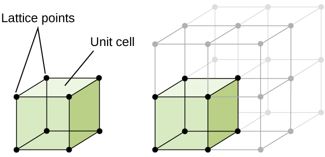
The structure of a crystalline solid, whether a metal or not, is best described by considering its simplest repeating unit, which is referred to as its unit cell. The unit cell consists of lattice points that represent the locations of atoms or ions. The entire structure then consists of this unit cell repeating in three dimensions, as illustrated in Figure 1.
https://opentextbc.ca/chemistry/chapter/10-6-lattice-structures-in-crystalline-solids/


0 Comments